Primitives addon
These functions are declared in the following header file. Link with allegro_primitives.
#include <allegro5/allegro_primitives.h>High level drawing routines
High level drawing routines encompass the most common usage of this addon: to draw geometric primitives, both smooth (variations on the circle theme) and piecewise linear. Outlined primitives support the concept of thickness with two distinct modes of output: hairline lines and thick lines. Hairline lines are specifically designed to be exactly a pixel wide, and are commonly used for drawing outlined figures that need to be a pixel wide. Hairline thickness is designated as thickness less than or equal to 0. Unfortunately, the exact rasterization rules for drawing these hairline lines vary from one video card to another, and sometimes leave gaps where the lines meet. If that matters to you, then you should use thick lines. In many cases, having a thickness of 1 will produce 1 pixel wide lines that look better than hairline lines. Obviously, hairline lines cannot replicate thicknesses greater than 1. Thick lines grow symmetrically around the generating shape as thickness is increased.
Pixel-precise output
While normally you should not be too concerned with which pixels are displayed when the high level primitives are drawn, it is nevertheless possible to control that precisely by carefully picking the coordinates at which you draw those primitives.
To be able to do that, however, it is critical to understand how GPU cards convert shapes to pixels. Pixels are not the smallest unit that can be addressed by the GPU. Because the GPU deals with floating point coordinates, it can in fact assign different coordinates to different parts of a single pixel. To a GPU, thus, a screen is composed of a grid of squares that have width and length of 1. The top left corner of the top left pixel is located at (0, 0). Therefore, the center of that pixel is at (0.5, 0.5). The basic rule that determines which pixels are associated with which shape is then as follows: a pixel is treated to belong to a shape if the pixel's center is located in that shape. The figure below illustrates the above concepts:
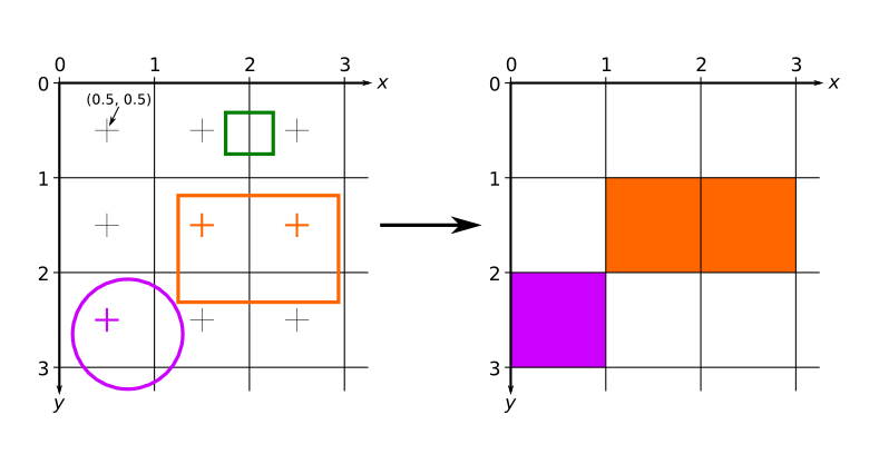
Diagram showing a how pixel output is calculated by the GPU given the mathematical description of several shapes.
This figure depicts three shapes drawn at the top left of the screen: an orange and green rectangles and a purple circle. On the left are the mathematical descriptions of pixels on the screen and the shapes to be drawn. On the right is the screen output. Only a single pixel has its center inside the circle, and therefore only a single pixel is drawn on the screen. Similarly, two pixels are drawn for the orange rectangle. Since there are no pixels that have their centers inside the green rectangle, the output image has no green pixels.
Here is a more practical example. The image below shows the output of this code:
/* blue vertical line */
al_draw_line(0.5, 0, 0.5, 6, color_blue, 1);
/* red horizontal line */
al_draw_line(2, 1, 6, 1, color_red, 2);
/* green filled rectangle */
al_draw_filled_rectangle(3, 4, 5, 5, color_green);
/* purple outlined rectangle */
al_draw_rectangle(2.5, 3.5, 5.5, 5.5, color_purple, 1);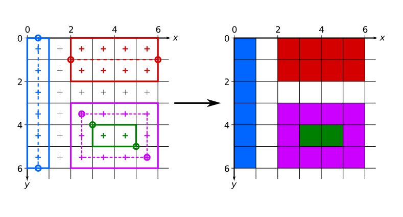
Diagram showing a practical example of pixel output resulting from the invocation of several primitives addon functions.
It can be seen that lines are generated by making a rectangle based on the dashed line between the two endpoints. The thickness causes the rectangle to grow symmetrically about that generating line, as can be seen by comparing the red and blue lines. Note that to get proper pixel coverage, the coordinates passed to the al_draw_line had to be offset by 0.5 in the appropriate dimensions.
Filled rectangles are generated by making a rectangle between the endpoints passed to the al_draw_filled_rectangle.
Outlined rectangles are generated by symmetrically expanding an outline of a rectangle. With thickness of 1, as depicted in the diagram, this means that an offset of 0.5 is needed for both sets of endpoint coordinates.
The above rules only apply when multisampling is turned off. When multisampling is turned on, the area of a pixel that is covered by a shape is taken into account when choosing what color to draw there. This also means that shapes no longer have to contain the pixel's center to affect its color. For example, the green rectangle in the first diagram may in fact be drawn as two (or one) semi-transparent pixels. The advantages of multisampling is that slanted shapes will look smoother because they will not have jagged edges. A disadvantage of multisampling is that it may make vertical and horizontal edges blurry. While the exact rules for multisampling are unspecified, and may vary from GPU to GPU it is usually safe to assume that as long as a pixel is either completely covered by a shape or completely not covered, then the shape edges will be sharp. The offsets used in the second diagram were chosen so that this is the case: if you use those offsets, your shapes (if they are oriented the same way as they are on the diagram) should look the same whether multisampling is turned on or off.
- al_draw_line
- al_draw_triangle
- al_draw_filled_triangle
- al_draw_rectangle
- al_draw_filled_rectangle
- al_draw_rounded_rectangle
- al_draw_filled_rounded_rectangle
- al_calculate_arc
- al_draw_ellipse
- al_draw_filled_ellipse
- al_draw_circle
- al_draw_filled_circle
- al_draw_arc
- al_calculate_spline
- al_draw_spline
- al_calculate_ribbon
- al_draw_ribbon
Low level drawing routines
Low level drawing routines allow for more advanced usage of the addon, allowing you to pass arbitrary sequences of vertices to draw to the screen. These routines also support using textures on the primitives with some restrictions. For maximum portability, you should only use textures that have dimensions that are a power of two, as not every videocard supports them completely. This warning is relaxed, however, if the texture coordinates never exit the boundaries of a single bitmap (i.e. you are not having the texture repeat/tile). As long as that is the case, any texture can be used safely. Sub-bitmaps work as textures, but cannot be tiled.
A note about pixel coordinates. In OpenGL the texture coordinate (0, 0) refers to the top left corner of the pixel. This confuses some drivers, because due to rounding errors the actual pixel sampled might be the pixel to the top and/or left of the (0, 0) pixel. To make this error less likely it is advisable to offset the texture coordinates you pass to the al_draw_prim by (0.5, 0.5) if you need precise pixel control. E.g. to refer to pixel (5, 10) you'd set the u and v to 5.5 and 10.5 respectively.